FPGA DSP Design & Verification with LLMs
Est. read time: 3 minutes | Posted: March 24, 2026 by John Gentile
Put simply, LLMs have gotten crazy good recently, going beyond typical software coding tasks, to even tackling HDL design. As those with experience in digital design know, this domain is not as simple to “code” as software: you’re really trying to coerce a chain of- often proprietary- EDA tools to map a desired function to a series of wires and hardware-specific primitives. Nonetheless, and even with much less open-source/high-quality training data, recent models have made leaps and bounds progress.
As an example, we want to design a canonical Numerically Controlled Oscillator for use in a DSP FPGA design. The following HDL was generated with Claude Opus 4.6 with the below simple prompt and no other project nor system context:
Create a simple Numerically Controlled Oscillator (NCO) for use in an FPGA in modern/idiomatic SystemVerilog
from IPython.display import Markdown as md
with open('./FPGA_NCO_files/nco.sv', 'r') as f:
    f_contents = f.read()

md(f"\n```verilog\n{f_contents}\n```")
// =============================================================================
// Numerically Controlled Oscillator (NCO)
// =============================================================================
//
// Architecture:
//   Phase Accumulator (N bits) → Truncated Phase (L bits) → Quarter-Wave LUT → Output
//
//   f_out = (FCW * f_clk) / 2^N
//   Phase resolution:  2π / 2^N
//   Spurious floor:    ~-6.02 * L dBc (truncation spurs before dithering)
//
// Quarter-wave symmetry exploits sin() symmetry to store only [0, π/2),
// reducing LUT depth from 2^L to 2^(L-2) entries.
//
// Parameters:
//   PHASE_ACC_W  – Phase accumulator width N (frequency resolution)
//   LUT_ADDR_W   – Truncated phase / LUT address width L (spur performance)
//   OUTPUT_W     – Output sample width (SNR ≈ 6.02*OUTPUT_W dB)
//   DITHER_EN    – Add 1-bit LFSR dither to truncated phase to whiten spurs
// =============================================================================

module nco #(
    parameter int PHASE_ACC_W = 32,
    parameter int LUT_ADDR_W  = 12,
    parameter int OUTPUT_W    = 16,
    parameter bit DITHER_EN   = 1'b1
) (
    input  logic                    clk,
    input  logic                    rst_n,

    // Control
    input  logic [PHASE_ACC_W-1:0]  fcw,          // Frequency control word
    input  logic [PHASE_ACC_W-1:0]  phase_offset, // Phase modulation input

    // Output — signed two's complement
    output logic signed [OUTPUT_W-1:0] sin_out,
    output logic signed [OUTPUT_W-1:0] cos_out,
    output logic                       valid
);

    // -------------------------------------------------------------------------
    // Derived parameters
    // -------------------------------------------------------------------------
    localparam int QUARTER_DEPTH = 2 ** (LUT_ADDR_W - 2); // π/2 worth of entries
    localparam int DISCARD_BITS  = PHASE_ACC_W - LUT_ADDR_W;

    // -------------------------------------------------------------------------
    // Phase accumulator
    // -------------------------------------------------------------------------
    logic [PHASE_ACC_W-1:0] phase_acc;

    always_ff @(posedge clk or negedge rst_n) begin
        if (!rst_n)
            phase_acc <= '0;
        else
            phase_acc <= phase_acc + fcw; // free-running, wraps modulo 2^N
    end

    // -------------------------------------------------------------------------
    // Optional truncation dither (LFSR-based)
    //   Adds pseudorandom noise into discarded LSBs to whiten truncation spurs.
    //   Galois LFSR, maximal-length for 16-bit: x^16 + x^14 + x^13 + x^11 + 1
    // -------------------------------------------------------------------------
    logic [15:0] lfsr;

    generate
        if (DITHER_EN) begin : gen_dither
            always_ff @(posedge clk or negedge rst_n) begin
                if (!rst_n)
                    lfsr <= 16'hACE1; // nonzero seed
                else
                    lfsr <= {lfsr[14:0], lfsr[15] ^ lfsr[13] ^ lfsr[12] ^ lfsr[10]};
            end
        end else begin : gen_no_dither
            assign lfsr = '0;
        end
    endgenerate

    // -------------------------------------------------------------------------
    // Phase truncation + offset + dither → LUT address
    // -------------------------------------------------------------------------
    logic [PHASE_ACC_W-1:0] phase_total;
    logic [LUT_ADDR_W-1:0]  phase_trunc;

    assign phase_total = phase_acc + phase_offset;

    // Add dither into the rounding region then truncate
    always_comb begin
        if (DITHER_EN && DISCARD_BITS > 0) begin
            automatic logic [PHASE_ACC_W-1:0] dithered;
            dithered    = phase_total + {{LUT_ADDR_W{1'b0}}, lfsr[DISCARD_BITS-1:0]};
            phase_trunc = dithered[PHASE_ACC_W-1 -: LUT_ADDR_W];
        end else begin
            phase_trunc = phase_total[PHASE_ACC_W-1 -: LUT_ADDR_W];
        end
    end

    // -------------------------------------------------------------------------
    // Quarter-wave LUT with symmetry decomposition
    //
    //   quadrant[1:0] = phase_trunc MSBs
    //   Q0 (00): sin(θ)        =  LUT[ addr          ]
    //   Q1 (01): sin(π-θ)      =  LUT[ ~addr         ]   (mirror)
    //   Q2 (10): sin(π+θ)      = -LUT[ addr          ]   (negate)
    //   Q3 (11): sin(2π-θ)     = -LUT[ ~addr         ]   (mirror+negate)
    //
    //   cos(θ) = sin(θ + π/2), so feed (phase_trunc + 2^(L-2)) into same logic.
    // -------------------------------------------------------------------------
    logic [1:0]               sin_quad, cos_quad;
    logic [LUT_ADDR_W-3:0]    sin_addr, cos_addr;
    logic                     sin_neg,  cos_neg;
    logic                     sin_mirror, cos_mirror;

    // Cosine phase = sin phase + π/2 (add 1 to quadrant)
    logic [LUT_ADDR_W-1:0] cos_phase;
    assign cos_phase = phase_trunc + LUT_ADDR_W'(QUARTER_DEPTH); // +2^(L-2)

    assign sin_quad   = phase_trunc[LUT_ADDR_W-1 -: 2];
    assign cos_quad   = cos_phase  [LUT_ADDR_W-1 -: 2];

    assign sin_mirror = sin_quad[0];
    assign cos_mirror = cos_quad[0];
    assign sin_neg    = sin_quad[1];
    assign cos_neg    = cos_quad[1];

    assign sin_addr = sin_mirror ? ~phase_trunc[LUT_ADDR_W-3:0]
                                 :  phase_trunc[LUT_ADDR_W-3:0];
    assign cos_addr = cos_mirror ? ~cos_phase[LUT_ADDR_W-3:0]
                                 :  cos_phase[LUT_ADDR_W-3:0];

    // -------------------------------------------------------------------------
    // LUT storage — inferred as block RAM (single-port, registered output)
    // Stores unsigned magnitude: round(2^(OUTPUT_W-1) - 1) * sin(2π·k / 4·DEPTH)
    // for k in [0, QUARTER_DEPTH).
    // -------------------------------------------------------------------------
    logic [OUTPUT_W-2:0] sin_lut [QUARTER_DEPTH]; // unsigned magnitude
    logic [OUTPUT_W-2:0] cos_lut [QUARTER_DEPTH];

    initial begin
        for (int k = 0; k < QUARTER_DEPTH; k++) begin
            sin_lut[k] = OUTPUT_W'($rtoi(
                $floor(((2.0 ** (OUTPUT_W - 1)) - 1.0)
                       * $sin(2.0 * 3.14159265358979323846 * real'(k) / real'(4 * QUARTER_DEPTH))
                       + 0.5)
            ));
            cos_lut[k] = sin_lut[k]; // same data, separate copy for dual-port inference
        end
    end

    // -------------------------------------------------------------------------
    // Pipeline stage 1: LUT read (registered for BRAM inference)
    // -------------------------------------------------------------------------
    logic [OUTPUT_W-2:0] sin_mag_r, cos_mag_r;
    logic                sin_neg_r, cos_neg_r;

    always_ff @(posedge clk) begin
        sin_mag_r <= sin_lut[sin_addr];
        cos_mag_r <= cos_lut[cos_addr];
        sin_neg_r <= sin_neg;
        cos_neg_r <= cos_neg;
    end

    // -------------------------------------------------------------------------
    // Pipeline stage 2: sign application → two's complement output
    // -------------------------------------------------------------------------
    always_ff @(posedge clk or negedge rst_n) begin
        if (!rst_n) begin
            sin_out <= '0;
            cos_out <= '0;
        end else begin
            sin_out <= sin_neg_r ? -signed'({1'b0, sin_mag_r})
                                 :  signed'({1'b0, sin_mag_r});
            cos_out <= cos_neg_r ? -signed'({1'b0, cos_mag_r})
                                 :  signed'({1'b0, cos_mag_r});
        end
    end

    // -------------------------------------------------------------------------
    // Valid strobe — accounts for 2-cycle pipeline latency
    // -------------------------------------------------------------------------
    logic [1:0] pipe_valid;

    always_ff @(posedge clk or negedge rst_n) begin
        if (!rst_n)
            pipe_valid <= '0;
        else
            pipe_valid <= {pipe_valid[0], 1'b1};
    end

    assign valid = pipe_valid[1];

    // -------------------------------------------------------------------------
    // Assertions (simulation only)
    // -------------------------------------------------------------------------
    // synthesis translate_off
    initial begin
        assert (LUT_ADDR_W >= 4)
            else $fatal(1, "LUT_ADDR_W must be >= 4 for quarter-wave decomposition");
        assert (PHASE_ACC_W >= LUT_ADDR_W)
            else $fatal(1, "PHASE_ACC_W must be >= LUT_ADDR_W");
        assert (OUTPUT_W >= 2)
            else $fatal(1, "OUTPUT_W must be >= 2 for signed representation");
    end
    // synthesis translate_on

endmodule
^ this looks pretty good for one-shot output! I mean, even with “simple” in the prompt, it went beyond the basic “phase accumulator -> LUT” design and right to implementing:
- A quarter-wave LUT to save on space with built-in value generation within the code (no external memory loading required)!
- Built-in LFSR for phase dithering to increase SFDR.
- Assertions to check for proper instantiation and usage.
But now we have to verify the design- let’s switch to Claude Code to give the context of our nco.sv HDL file and let it generate a testbench and Makefile for use by Verilator:
@nco.sv is a simple Numerically Controlled Oscillator in SystemVerilog. We want to write a simple unit test to verify basic output- write a simple SystemVerilog testbench as well as Makefile targeting Verilator simulator (Verilator is already installed on the system).
Claude goes right to work making the following testbench, but not without using it’s Bash tool first to find the current Verilator version installed ($$ verilator --version) to make sure the testbench matches supported conventions (brilliant!):
with open('./FPGA_NCO_files/nco_tb.sv', 'r') as f:
    f_contents = f.read()

md(f"\n```verilog\n{f_contents}\n```")
// =============================================================================
// NCO Testbench
// =============================================================================
// Basic verification:
//   1. Reset behavior — outputs zero, valid deasserted
//   2. Valid strobe asserts after 2-cycle pipeline latency
//   3. DC check — FCW=0 produces constant output
//   4. Sine/cosine quadrature — cos leads sin by ~90°
//   5. Output bounded within signed range
// =============================================================================

module nco_tb;

    // Use small parameters for fast simulation
    localparam int PHASE_ACC_W = 16;
    localparam int LUT_ADDR_W  = 8;
    localparam int OUTPUT_W    = 12;

    logic                          clk;
    logic                          rst_n;
    logic [PHASE_ACC_W-1:0]       fcw;
    logic [PHASE_ACC_W-1:0]       phase_offset;
    logic signed [OUTPUT_W-1:0]   sin_out;
    logic signed [OUTPUT_W-1:0]   cos_out;
    logic                          valid;

    nco #(
        .PHASE_ACC_W (PHASE_ACC_W),
        .LUT_ADDR_W  (LUT_ADDR_W),
        .OUTPUT_W    (OUTPUT_W),
        .DITHER_EN   (1'b0)         // disable dither for deterministic checks
    ) dut (
        .clk          (clk),
        .rst_n        (rst_n),
        .fcw          (fcw),
        .phase_offset (phase_offset),
        .sin_out      (sin_out),
        .cos_out      (cos_out),
        .valid        (valid)
    );

    // Clock: 10 ns period
    initial clk = 0;
    always #5 clk = ~clk;

    // Max positive value the LUT can produce
    localparam int MAX_MAG = (2 ** (OUTPUT_W - 1)) - 1;

    int errors = 0;

    // Helper: run N clock cycles
    task automatic tick(int n = 1);
        repeat (n) @(posedge clk);
    endtask

    // -------------------------------------------------------------------------
    // Main test sequence
    // -------------------------------------------------------------------------
    initial begin
        $dumpfile("nco_tb.vcd");
        $dumpvars(0, nco_tb);

        // ---- Init ----
        rst_n        = 0;
        fcw          = '0;
        phase_offset = '0;
        tick(4);

        // ---- Test 1: Reset behaviour ----
        $display("[TEST 1] Reset behavior");
        if (sin_out !== '0 || cos_out !== '0) begin
            $display("  FAIL: outputs not zero in reset (sin=%0d cos=%0d)", sin_out, cos_out);
            errors++;
        end
        if (valid !== 1'b0) begin
            $display("  FAIL: valid asserted during reset");
            errors++;
        end

        // ---- Release reset ----
        @(posedge clk) rst_n <= 1;

        // ---- Test 2: Valid strobe latency ----
        $display("[TEST 2] Valid strobe latency");
        tick(1);
        if (valid !== 1'b0) begin
            $display("  FAIL: valid high too early (cycle 1)");
            errors++;
        end
        tick(1);  // 2 cycles after reset release
        if (valid !== 1'b1) begin
            $display("  FAIL: valid not asserted after 2 pipeline stages");
            errors++;
        end

        // ---- Test 3: FCW=0 → constant output ----
        $display("[TEST 3] FCW=0 constant output");
        fcw = '0;
        tick(10);
        begin
            logic signed [OUTPUT_W-1:0] s0, c0, s1, c1;
            s0 = sin_out; c0 = cos_out;
            tick(5);
            s1 = sin_out; c1 = cos_out;
            if (s0 !== s1 || c0 !== c1) begin
                $display("  FAIL: output changed with FCW=0");
                errors++;
            end
        end

        // ---- Test 4: Run a tone — check outputs stay bounded ----
        // FCW = 2^(N-4) gives f_out = f_clk/16 — completes one full cycle in 16 samples
        $display("[TEST 4] Bounded output with active tone");
        fcw = 16'(1 << (PHASE_ACC_W - 4));
        tick(4); // flush pipeline
        begin
            int bounded_ok = 1;
            for (int i = 0; i < 64; i++) begin
                tick(1);
                if (sin_out > MAX_MAG || sin_out < -MAX_MAG ||
                    cos_out > MAX_MAG || cos_out < -MAX_MAG) begin
                    $display("  FAIL: output out of range at sample %0d (sin=%0d cos=%0d)",
                             i, sin_out, cos_out);
                    bounded_ok = 0;
                    errors++;
                end
            end
            if (bounded_ok) $display("  PASS: all samples within [-%0d, %0d]", MAX_MAG, MAX_MAG);
        end

        // ---- Test 5: Quadrature relationship ----
        // With a slow tone, sample near zero-crossing of sin where cos should be near peak
        $display("[TEST 5] Quadrature check (cos leads sin by ~90 deg)");
        fcw = 16'(1 << (PHASE_ACC_W - 4)); // same tone
        rst_n = 0;
        tick(4);
        @(posedge clk) rst_n <= 1;
        tick(3); // pipeline flush — phase_acc ≈ 0 at this point
        // Near phase=0: sin≈0, cos≈+peak
        begin
            if (!(cos_out > sin_out)) begin
                $display("  FAIL: at phase~0 expected cos > sin (sin=%0d cos=%0d)", sin_out, cos_out);
                errors++;
            end else begin
                $display("  PASS: cos > sin near phase 0 (sin=%0d cos=%0d)", sin_out, cos_out);
            end
        end

        // ---- Summary ----
        tick(2);
        if (errors == 0)
            $display("\n=== ALL TESTS PASSED ===");
        else
            $display("\n=== %0d ERROR(S) ===", errors);

        $finish;
    end

endmodule
Now Claude knows it needs to generate a Makefile to launch the simulation and check outputs:
with open('./FPGA_NCO_files/Makefile', 'r') as f:
    f_contents = f.read()

md(f"\n```makefile\n{f_contents}\n```")
# NCO Verilator testbench
# Usage:
#   make        — build and run the testbench
#   make wave   — open waveform in GTKWave (if installed)
#   make clean  — remove generated files

TOP      := nco_tb
SOURCES  := nco.sv nco_tb.sv
OBJ_DIR  := obj_dir

.PHONY: all run wave clean

all: run

# Verilator compile: SystemVerilog, enable timing, trace (VCD)
$(OBJ_DIR)/V$(TOP): $(SOURCES)
	verilator --binary --timing -j 0 --trace \
		-Wno-WIDTHEXPAND -Wno-WIDTHTRUNC -Wno-INITIALDLY -Wno-IMPLICITSTATIC \
		--top-module $(TOP) $(SOURCES)

run: $(OBJ_DIR)/V$(TOP)
	./$(OBJ_DIR)/V$(TOP)

wave: run
	gtkwave $(TOP).vcd &

clean:
	rm -rf $(OBJ_DIR) $(TOP).vcd
It then runs the Makefile, sees an error related to IMPLICITSTATIC lifetime, adjusts the Makefile to ignore that flag in the one variable, and re-runs to show a successul testbench execution:
- V e r i l a t i o n   R e p o r t: Verilator 5.046 2026-02-28 rev vUNKNOWN-built20260228
- Verilator: Built from 0.061 MB sources in 3 modules, into 0.093 MB in 9 C++ files needing 0.000 MB
- Verilator: Walltime 2.420 s (elab=0.006, cvt=0.011, bld=2.392); cpu 0.021 s on 12 threads; allocated 11.875 MB
./obj_dir/Vnco_tb
[TEST 1] Reset behavior
[TEST 2] Valid strobe latency
[TEST 3] FCW=0 constant output
[TEST 4] Bounded output with active tone
  PASS: all samples within [-2047, 2047]
[TEST 5] Quadrature check (cos leads sin by ~90 deg)
  PASS: cos > sin near phase 0 (sin=783 cos=1871)

=== ALL TESTS PASSED ===
- nco_tb.sv:156: Verilog $finish
Let’s go one step further- let’s have Claude use it’s Python skills to generate a cocotb testbench to numerically verify the NCO output:
Now that we have a basic unit testbench in @nco_tb.sv let’s create a
cocotbPython verification file that we can run to plot the output spectrum of @nco.sv and measure the SFDR.
This gives us another Makefile to launch the cocotb sim and then the following Python testbench:
with open('./FPGA_NCO_files/test_nco.py', 'r') as f:
    f_contents = f.read()

md(f"\n```python\n{f_contents}\n```")
"""
cocotb testbench for NCO – captures output samples, plots the spectrum, and measures SFDR.
Run with:
make -f Makefile.cocotb
Requires: cocotb, cocotb-test, numpy, matplotlib
Simulator: Icarus Verilog (iverilog) or Verilator with cocotb support
"""
import cocotb
from cocotb.clock import Clock
from cocotb.triggers import RisingEdge, ClockCycles
import numpy as np
import matplotlib.pyplot as plt
# ---------------------------------------------------------------------------
# Helpers
# ---------------------------------------------------------------------------
def signed_val(signal, width):
"""Convert an unsigned cocotb signal value to signed Python int."""
val = signal.value.integer
if val >= (1 << (width - 1)):
val -= 1 << width
return val
async def reset_dut(dut, cycles=4):
"""Assert reset for *cycles* clock edges, then release."""
dut.rst_n.value = 0
dut.fcw.value = 0
dut.phase_offset.value = 0
await ClockCycles(dut.clk, cycles)
dut.rst_n.value = 1
await ClockCycles(dut.clk, 2) # wait for pipeline to fill
# ---------------------------------------------------------------------------
# Parameters (must match the cocotb runner / Makefile generics)
# ---------------------------------------------------------------------------
PHASE_ACC_W = 16
LUT_ADDR_W = 8
OUTPUT_W = 12
# ---------------------------------------------------------------------------
# Test: Capture tone, plot spectrum, measure SFDR
# ---------------------------------------------------------------------------
@cocotb.test()
async def test_nco_spectrum(dut):
"""Run the NCO at a known tone, capture samples, compute FFT, and report SFDR."""
clock = Clock(dut.clk, 10, units="ns") # 100 MHz
cocotb.start_soon(clock.start())
await reset_dut(dut)
# --- Choose FCW for a bin-centered tone ---
# N_samples must be a power of 2 for a clean FFT.
N = 4096
# Pick a tone that lands exactly on an FFT bin to avoid spectral leakage:
# bin_index * 2^PHASE_ACC_W / N = FCW
bin_index = 107 # prime-ish, away from DC and Nyquist
fcw_val = int(bin_index * (2**PHASE_ACC_W) / N)
dut.fcw.value = fcw_val
f_clk = 100e6
f_tone = fcw_val * f_clk / 2**PHASE_ACC_W
dut._log.info(
f"FCW = {fcw_val} → f_tone = {f_tone / 1e6:.4f} MHz (bin {bin_index})"
)
# Let the pipeline settle after changing FCW
await ClockCycles(dut.clk, 4)
# --- Collect samples ---
sin_samples = np.zeros(N, dtype=np.float64)
cos_samples = np.zeros(N, dtype=np.float64)
for i in range(N):
await RisingEdge(dut.clk)
sin_samples[i] = signed_val(dut.sin_out, OUTPUT_W)
cos_samples[i] = signed_val(dut.cos_out, OUTPUT_W)
# --- Compute power spectrum (dBFS) ---
window = np.blackman(N)
sin_windowed = sin_samples * window
spectrum = np.fft.rfft(sin_windowed)
mag = np.abs(spectrum) / (np.sum(window) / 2) # normalize
mag_db = 20 * np.log10(mag + 1e-20) # dBFS (relative to full-scale sine)
# Normalize so the fundamental is 0 dBFS
fund_bin = np.argmax(mag_db)
mag_db -= mag_db[fund_bin]
freqs_mhz = np.fft.rfftfreq(N, d=1.0 / f_clk) / 1e6
# --- Measure SFDR ---
# Exclude DC (bin 0) and a ±3-bin window around the fundamental
spur_mask = np.ones(len(mag_db), dtype=bool)
spur_mask[0] = False # ignore DC
guard = 3
lo = max(1, fund_bin - guard)
hi = min(len(mag_db) - 1, fund_bin + guard)
spur_mask[lo : hi + 1] = False
spur_peak_bin = np.argmax(mag_db[spur_mask])
# Map back to absolute bin index
spur_abs_bin = np.arange(len(mag_db))[spur_mask][spur_peak_bin]
sfdr = mag_db[fund_bin] - mag_db[spur_abs_bin]
dut._log.info(f"Fundamental bin: {fund_bin} ({freqs_mhz[fund_bin]:.3f} MHz)")
dut._log.info(
f"Largest spur bin: {spur_abs_bin} ({freqs_mhz[spur_abs_bin]:.3f} MHz)"
)
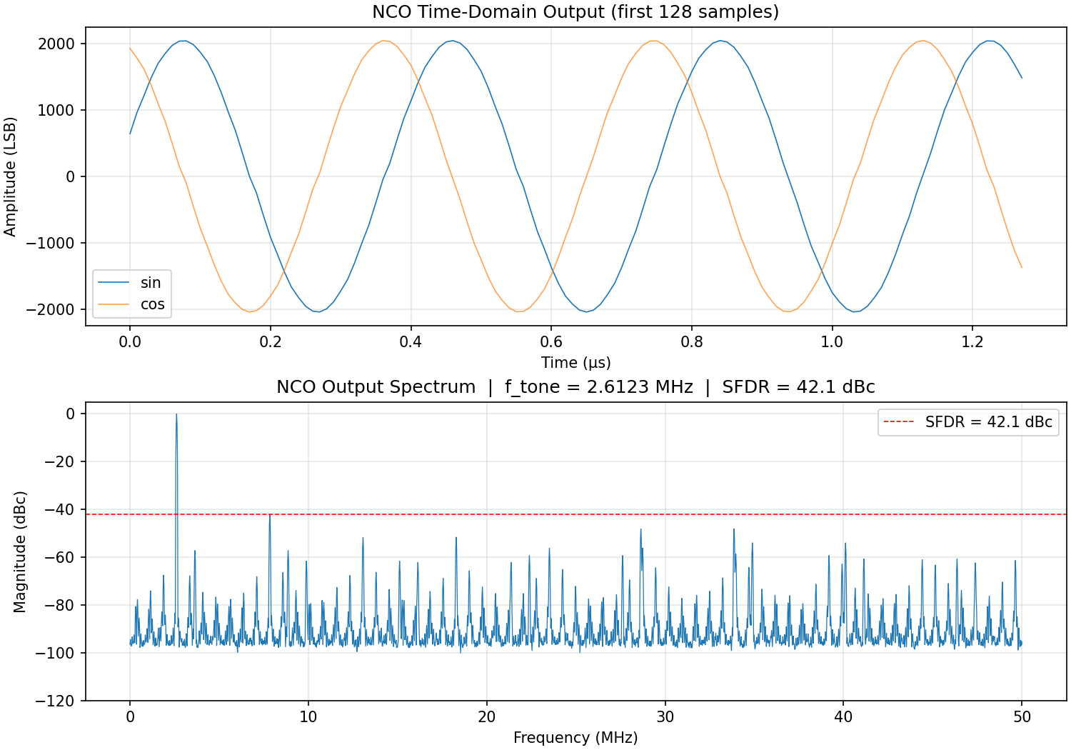
dut._log.info(f"SFDR = {sfdr:.1f} dBc")
# --- Plot ---
fig, axes = plt.subplots(2, 1, figsize=(10, 7), constrained_layout=True)
# Time-domain (first 128 samples)
t_us = np.arange(128) * (1 / f_clk) * 1e6
axes[0].plot(t_us, sin_samples[:128], label="sin", linewidth=0.8)
axes[0].plot(t_us, cos_samples[:128], label="cos", linewidth=0.8, alpha=0.7)
axes[0].set_xlabel("Time (µs)")
axes[0].set_ylabel("Amplitude (LSB)")
axes[0].set_title("NCO Time-Domain Output (first 128 samples)")
axes[0].legend()
axes[0].grid(True, alpha=0.3)
# Spectrum
axes[1].plot(freqs_mhz, mag_db, linewidth=0.6)
axes[1].axhline(
-sfdr, color="r", linestyle="--", linewidth=0.8, label=f"SFDR = {sfdr:.1f} dBc"
)
axes[1].set_xlabel("Frequency (MHz)")
axes[1].set_ylabel("Magnitude (dBc)")
axes[1].set_title(
f"NCO Output Spectrum | f_tone = {f_tone / 1e6:.4f} MHz | SFDR = {sfdr:.1f} dBc"
)
axes[1].set_ylim([-120, 5])
axes[1].legend()
axes[1].grid(True, alpha=0.3)
fig.savefig("nco_spectrum.png", dpi=150)
dut._log.info("Saved plot to nco_spectrum.png")
plt.close(fig)
# --- Pass/fail ---
# With 8-bit LUT address (quarter-wave), theoretical spur floor ~ -6*8 = -48 dBc.
# Require at least 40 dBc as a sanity check.
MIN_SFDR = 40.0
assert sfdr >= MIN_SFDR, f"SFDR {sfdr:.1f} dBc below threshold {MIN_SFDR} dBc"
dut._log.info("PASS")
This gives the following plot and SFDR measurement output:
Summary
In the end, this isn’t a perfect solution- there’s some quirks in the dither logic and we need to pass through a tool like Vivado’s synthesis flow to know if we can map this to a target FPGA- but this is a massive and quick start to a DSP FPGA design that we can iterate on further. And again, this was done with no system or other context- the true power of LLMs in this domain, and moreover agentic tools like Claude Code, is:
- Feeding the rest of your codebase and documentation as context (especially useful in complex DSP projects where we have documentation like waveform specs and ICDs, as well as modeling code, like Matlab).
- Specifying HDL testbench coverage, coding-style, linting, etc. requirements as part of system context (like in Claude Code’s
CLAUDE.mdinstruction file)- LLMs are particularly useful at the mundane tasks of documenting blocks, adding tests, formatting, etc. - Hooking up other tools, like Vivado
tclsteps, as Model Context Protocol (MCP) tools available to be called by the LLM.
Maintained by John Gentile • Found a problem on this site? File an Issue
This work is licensed under a Creative Commons Attribution 4.0 International License.![]()